If your battery fans die out then you have two options: Pay the $300 to get replacements.. or pay ~50 to repair them.
In my case, my motors works perfectly fine, it was just the controller that had failed. I replaced the controller with a generic aftermarket one and it worked great. The one down side is that the motors no longer have their speed control. When they turn on, they are on full blast until the computer turns them back off again.
The resistors, transistors, and diodes I already had, but i listed Amazon links in case others don't have any laying around. The relay i used was from Autozone and had part number RL44. While i listed relays from Amazon for consistency, I'd recommend getting the same one i did from Autozone just so you know yours has the same coil draw. The RL44 relay had 133mA draw and was the basis for choosing the transistor/resistor.
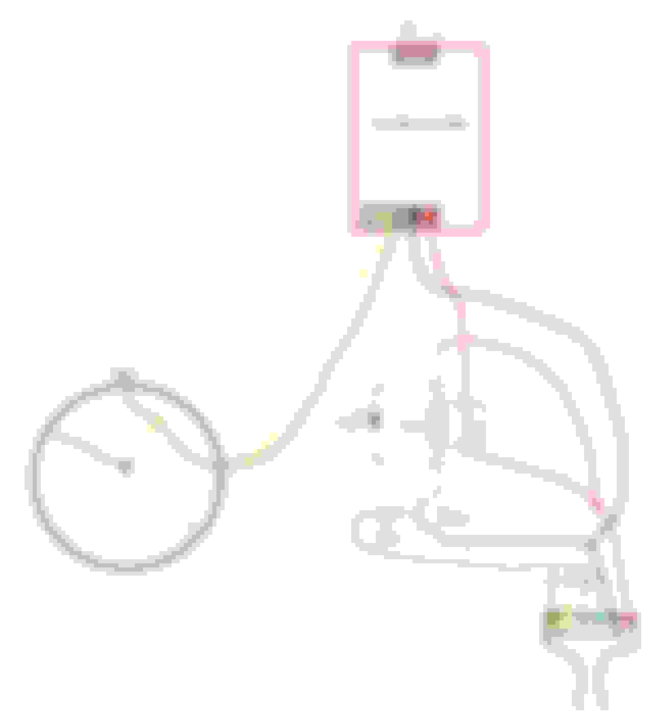
Schematic:
DISASSEMBLY:
Step 1: Remove the 3 nuts on the bottom of the fan so you can remove the bracket and ground wire
Step 2: Flip it over and remove the 9 Phillips head screws to allow you to separate the two halves of the shell.
Step 3: Place a small drop of oil on the inside lip of the lock washer to help it slide better. Get a pair of pliers so you can firmly grip the outside edge of the washer, but do not squeeze too hard - you don't want to mangle it. Twist back and forth while you lift and it should slowly slide off.
Step 4: Figure out a way to remove the fan cage from the spindle. I used a long screwdriver and slowly worked it upward by twisting the screwdriver. Take care not to break the plastic cage. Thankfully, it was flexible rather than brittle.
Step 5: Remove the 3 larger screws on the metal fan housing. These are longer screws that go to the rubber bushings on the other side.
Step 6: Pull the motor from the plastic housing and then remove the 3 smaller screws
Step 7: Gently lift up on the top plate. The plate is glued to the top of a heatsink on the board inside. Slide a screwdriver in the gap you created by lifting the plate and pry the heatsink down off of the top plate. Note that the heatsink is directly opposite where the wires enter the housing. You wont be using the heatsink again, so don't worry about damaging it. however, try not to lift too high on the top plate when you're working the heatsink free. You don't want to break any of the windings on the motor.
Step 8: With the top plate removed, you should now see the circuit board. It is connected to the motor by 6 wires that lead to the coils. Desolder these. Each wire is wrapped around a stem on the board. Take your time to unravel them while you're desoldering. You'll want to keep as much slack as you can get, so avoid cutting them.
You're done with disassembly. You can pull the rotor out of the motor if you'd like. Be aware that the black part of the rotor is a magnet, so it'll want to catch on the metal casing. The rotor has 2 bearings, be sure to test both of them to see if they're bad. Replace them if they need it (mine were fine).
TESTING:
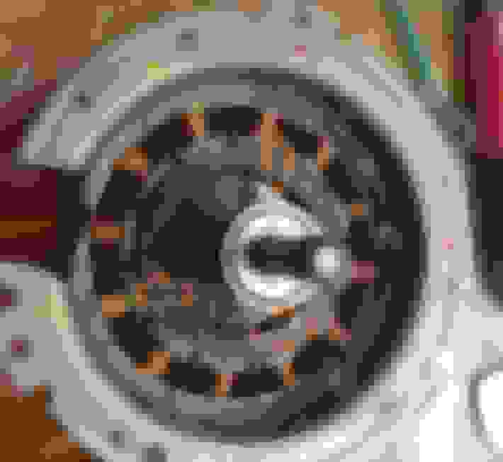
Before you start soldering, you should first verify that the windings are good. Take a look at the first picture of the Repair. You can see how i marked each phase with colored dots (yellow, orange, black). Take your multimeter do the following tests:
* Yellow to yellow for continuity
* Orange to orange for continuity
* Black to black for continuity
* Yellow to orange
* Yellow to black to ensure no short
* Orange to black to ensure no short
* Yellow to the metal case to ensure no short
* Orange to the metal case to ensure no short
* Black to the metal case to ensure no short
If all of the above tests passed then you're ready to start the repair. If you found a short then you can rewind the windings. I had to do this on one of my motors because i pried up on the circuit board without desoldering the windings first. Each of the windings broke too far down to reach so i had to rewind the whole motor. It's not hard, but it sure is time consuming.
REPAIR:
[ Each solder should be protected by either heat shrink tubing (preferred) or electrical tape. ]
Step 1: Straighten out each of the 6 leads with a pair of needle nose pliers. Take note that one side of each color will exit on the outside of the coil, whereas the other side of the color will exit from the center of the coil. Take the 3 centers (as marked in picture) and solder enough wire to the ends of them so you can later connect all 3 together and still be able to tuck them out of the way.
Step 2: Cut the wires so that they're all the same length. Now solder them together.
Step 3: Spread the connection apart so you can tuck each wire out of the way. Try to use the white plastic tabs to pin the wire against the wall. You don't want the wire to touch the rotor while it's spinning.
Step 4: Cut 3 equal lengths of wire. Solder each wire to one of the 3 remaining leads coming from the motor. Place the rubber grommet back in the metal case and tuck 3 wires into it so they don't get damaged by the metal case.
Step 5: Double-check that all 6 wires are seated in a nice place. Screw the top plate back on.
Step 6: Take your Ford circuit board and cut the wires off as close to the board as you can. The board is now garbage. Tape up or shrink wrap the ends of the Gray, Yellow, and Tan wires. These wires will not be needed for the repair.
Step 7: The controller board company has tinned the ends of the wires on their connector. This makes it an incredible pain to strip the wires. Cut the tinned tips off of the wire (go a few millimeters into the insulation since the wires soak up the solder a bit). Strip each of the wires, but be careful not to pull them out of the connector.
Step 8: Solder the White, Green, and Yellow lines from the motor to the fan controller's connector. You can now test that the fan controller works properly by connecting the Red/Black wires to 12v. Be sure to connect the potentiometer and spin it all the way clockwise. The fan should spin up and a red light should illuminate on the board. If it doesn't double-check your wiring and possibly send it back as defective.
Step 9: Crimp a blue female spade onto the controller's Red wire. You can connect this to Pin 87 on the relay.
Step 10: Solder the resistor to the middle pin on the transistor. Try to solder quickly so you don't overheat either component. Use alligator clips as heatsinks if you think you may take too long.
Step 11: Take the Ford harness and solder on 2 extensions to the Red wire. One of the extensions should be a similar gauge as the original. Crimp a blue connector onto this wire and you can then connect it to pin 30 on the relay. The other wire can be a smaller gauge.
Step 12: Take the black wire from the Ford harness and connect two extensions. One extension should be similar gauge. This one gets connected directly to the Black wire on the Controller's connector. The other wire can be a smaller gauge. It will get connected to pin 1 of the transistor. If you're holding the transistor so the flat face is toward you then pin 1 is on the LEFT (i have it backwards in my picture).
Step 13: Connect the Blue wire from the Ford harness to the end of your resistor. This is the trigger wire from the computer that turns on the circuit when the fans are needed.
Step 14: Connect a wire to the last leg of the transistor (pin 3 .. if looking at the flat face then it's on your Right). Now connect 2 extensions to that wire (can be smaller gauge). Crimp a red spade onto one extension and connect it to pin 86 on the relay. Solder your diode onto the other extension. It is important that the end of the diode with the stripe should be facing Away from the wire.
Step 15: Grab your Red wire from the Ford harness (you already put on 2 extensions). Take the bar extension and add 2 more extensions to the end of it (can be smaller gauge). Connect a spade to the end of one wire and connect it to pin 85 of the relay. Connect the other final wire to the end of your diode (the end with the stripe).
Step 16: Your circuit is now done! Here's how the final assembly should look.
Step 17: If you want your fans to always run at full speed (i did) then you can cut your the potentiometer off of its wire. Then solder the 2 wires together like in the schematic to set it at full speed. If you want it to run at some other speed then you have a couple options. You could spin the Pot so that it is on the speed you want and just leave it connected. Or, you can use a multimeter to read the resistance between the two main wires (the ones connected in schematic). Then cut the Pot off the line and solder in a resistor between those 2 wires to match the setting you liked.
Step 18: There are a ton of electrical connections exposed on the board and the relay. My choice was to cut a strip of blue shop towel and wrap it around each the relay and board individually. I then used electrical tape to secure the towel to each component. This should prevent it from touching anything in the car.
Step 19: Reassemble the fans (reverse order of the Disassembly guide)
Step 20: Install the fans into the car and give it a test. Be sure to tuck everything out of the way so that the black plastic shroud that goes over the fans doesn't hit anything. Be careful of your transistor leads. They're fragile.. i broke one when re-situating things and had to replace it. Note that if you just started your car and have yet to move the car then the fans will not turn on until the battery hits 85F. If the fans are over 75F and you drive over 10mph (even for a second) then it will turn on the fans until they drop below 70F. I would just start the car and drive to the end of my driveway and the fans would kick on and then i'd backup to my parking spot again and leave the car running while i evaluated the results.
Do you notice significant noise in a quiet vehicle (i.e. radio off) with the fans running at full speed and the car idle?
How long would you estimate from beginning to end (ignoring all of the investigative time you put in)?
I'm always surprised that sellers of salvaged fans on eBay seem to think they're worth $130+ each when it's $300 to get a set of 2 new fans from Ford (or under $500 for a complete salvage battery). I suppose if only one fan went bad that might be an option, but you're getting a fan that could fail at any time. Plus once you go to the hassle of opening up the battery pack you might as well replace (or repair) both fans.
If you're not intimidated by relatively simple electrical work, this repair seems like a good alternative if on a tight budget (or if just too stubborn to give Ford more money for their unreliable controller boards).
After you've run with your repaired fans for a few weeks, please update this to let us know if you notice any issues.
>>Do you notice significant noise in a quiet vehicle (i.e. radio off) with the fans running at full speed and the car idle?
I haven't done much driving yet, but it seems tolerable to me. Granted, noise tolerance is a relative thing so others may feel differently. With only around the block/driveway testing I noticed that the sound level and current draw changed when it dropped into full EV while parked. Likewise current draw has only been around 2A in ICE and 1.3A in EV at 77F. I really hadn't expected this. Rather, i thought it was just going to draw a constant 7A since this was the highest i observed on a factory fan. After I had finished the first motor repair i ran it side-by-side with a factory motor.. the sound and draw were surprisingly similar. It seems as though the available current might be throttled and the pwm line may have been just secondary information. We'll see how it goes whenever i do more driving, but at the moment it appears that the fans may still be speed controlled. I'll leave the 'max fan speed' disclaimer in the initial post until I confirm otherwise.
Now that the fans are working again i've gone ahead and sealed the battery compartment back up. This makes it so i can't do any more current draw tests, but I will say that i did notice a marked improvement in noise level with each component i put back in place. Back when i was experiencing 100F temps and the fan was drawing 7a while driving I can certainly say that the fan noise was incredibly loud with the fan just sitting in the cabin.
>>How long would you estimate from beginning to end (ignoring all of the investigative time you put in)?
Oh goodness. If you count all of the data gathering from the car and research to build the circuit then it's probably in the neighborhood of around 40-60 hours. I have some research OCD so i'll spend entire days just reading up on things. However, for someone to do the fan removal/teardown/repair/install i'd estimate somewhere around 6-7 hours with them taking their time. If you plow through it then probably more like 3-4h.
I'll try to remember to post an update next month. Though, if i forget then someone is more than welcome to post a reminder.
Can you post an update when you get the chance? Have there been any changes to fan speed based on demand?
They consistently turns on/off at the proper times, so the triggering portion works great. When on, the fans run at a constant speed and do not increase/decrease based on demand (as expected). The unexpected piece is that the fans run at a 2 amp draw, which is roughly 30% of their max speed. The plus side to this is that 30% is nice and quiet to the point that you can't hear it over music. The trouble is that it at this slower speed they can still get overwhelmed by higher ambient temperatures. It worked great for temps in the 70s as well as a day that was 80. However, it wasn't able to keep up when we had an 85 degree day.
The 30% speed was actually an accident. When i connected the fans directly to my test battery in the garage they ran at 100%. I'm fairly sure the fans are running slower because the relay's coil is powered by the same 12v line that the fans run on. I do plan on revising the circuit to either get them running at full speed or to get the stock temperature-rated speed control working again, but likely wont start toying with it for a couple months. I'll be sure to update the guide once I have a solution for myself.
Now that it's fall/winter weather the fans work perfectly fine. I don't imagine they'll struggle to keep up until sometime around june/july.
https://www.digikey.com/product-deta...164-ND/4691839 Supposedly this Panasonic ACVN is a newer model that has a 66.7mA coil. It's looks pretty robust. Would be nice to find a harness for it because it looks tight.
Based on that Panasonic CB data, coil resistance is 89.5ohm. It turns on at 1.2v. I might try adding in a 100ohm or higher potentiometer on the ACC side before the coil to see if/how it has any effect. Worse thing that could happen is the coil doesn't get enough current to turn on, I think.
With the cooler weather setting in, I guess we won't find out for a while. The earliest I could get to this is about 3 weeks from now. Then there's Thanksgiving...
Anyway, I must say I really appreciate the work you have put into this. Thanks.
(EDIT)
I just found your previous thread https://www.greenhybrid.com/forums/f...reation-31683/
Use the Switched hot (Yellow or blue, looks like you may have switched them) to energize the relay coil while the red drives the fan itself.
I'll be digging into mine shortly, hopefully I'll have more to add
It's starting to get warm again, so I'd love to hear any updates you may have
Thom
Last edited by Thommyknocker; 03-27-2019 at 02:41 PM.
Unfortunately, neither the yellow nor blue will work to directly energize the coil. Yellow isn't 12v and blue's current is too low (which is why i went to the BJT pre-relay switch). My intentions are to do a test where i disable one of the fans and use it's red wire to power the coil on the other fan.. thus leaving the working fan to use full current on its own red line. If that solves the speed problem then i'll just hunt out another nearby 12v source that i can use to feed the coils with.
The mosfet could perhaps solve the relay problem but i'm not sure how much heat it'll generate. Both the BJT and mechanical relay are able to be handled comfortably. If you try it out then let us know if they stay cool enough to be safe to use. They're certainly a cheaper and easier solution to understand than my relay approach.
I still plan on trying to figure out a way to make use of the PWM signal for fan speed. However, i was intending on waiting til the weather got warm enough to test via the car. I don't have an electronics background so it'll have to be something else i research til i figure out. Feel free to post and save me the trouble if you already know how
I've tried a few times to reply, guess I need moderator approval?
Quoting you actually posted, so I'll give it a go at remembering what I had to say
Dug into mine today. I'm not getting 12 volt on the blue, even when the key is on.
Any special trick to make the fans spin?
It might not even be applying voltage yet. It's only about 60 deg today.
That mosfet I posted earlier is way overkill. But mosfets react to voltage, not current like a coil.
It wouldn't be switching high current, so it wouldnt get warm
I got one of my fans appart, and my neighbor is more knowledgeable. On the controller board, next to the red wire input. There is a little white square smd. It's a fuse. Mine is blown, so I'll bypass it for now and see if the rest of the board works. I may have a crusty connection on the component under the heat sink. I'll explore that later
Last edited by Thommyknocker; 03-31-2019 at 07:49 PM.
When you click on links to various merchants on this site and make a purchase, this can result in this site earning a commission. Affiliate programs and affiliations include, but are not limited to, the eBay Partner Network.
 09-23-2018, 02:07 AM