HCH1 DIY IMA Reconditioning
#1
 04-03-2017, 10:26 PM


I wanted to share my experience reconditioning my HCH1 IMA battery via DIY grid charger. I am certainly no expert on any of this, so if there any incorrect information, please forgive me. This is only my experience, not necessarily a guide for anyone else. In general I followed the procedures on https://hybridautomotive.com/pages/recon (I am not in any way affiliated with any company or group, just a regular Joe). The grid charger was based on the recommendations in these forums from S Keith. Some background; purchased a 2005 Honda Civic Hybrid in Nov 2014 with 160k miles and the original IMA battery. Over the next 2 years and 50k miles I had an occasional P2000 (1/yr) but overall no IMA issues. In March of 2017 the car sat for 1 week and the CEL/IMA lights came on for P1600 / P1433. When I couldn�t just clear the codes I knew it was time to act.
Building the charger for the HCH1 was actually quite simple mostly because the MeanWell LPC-100-350 is a single unit. I wanted to monitor the voltage and current for both charge and discharge so created it in a simple modular fashion. There are basically 3 sections, the battery, the monitoring module, the charger or discharger. Each section was wired using standard AC plugs on input and output. I didn�t try to make anything fancy, just functional. Total cost was less than $100 for everything.
(See Diagram.png, IMG_0991.JPG, IMG_0992.JPG)
I won�t cover removing the battery, but it was pretty straight forward process which is outlined nicely on https://hybridautomotive.com/pages/install-c1. However their procedure is meant for installing their charger and wiring harness so not all of it applies. Skip any steps that require cutting wires or getting into the trunk, everything can be done from inside the vehicle.
With everything on the table and the box fan blowing directly on the battery, I started the initial charge and recorded values into a spreadsheet every 5 minutes. I also used an IR thermometer to check temps on the fan side of the battery and another on the opposite side. In hindsight I got a bit nervous during the first charge and cut the charge short after 1 hour at 163v. Swapping out the charger for the single bulb discharger w/150 watt bulb I recorded the values until I reached 120 volts (1.0v / cell). Part way through the discharge I decided that I couldn�t continue recording values every 5 minutes and dropped to 10 minutes. I was quite surprised to see the voltage drop to 120v in less than 1 hour 20 minutes with the relatively low current of the single 150 watt bulb. If my thinking is right that is roughly 1.2-1.5Ah capacity, because of the incomplete initial charge I take this with a grain of salt. Even if this would have been 2.0Ah that is a far cry from the original rating of 6.5Ah.
Given how fast the first charge went, I started the second round. After 2 hrs it was obvious that this was going to take longer than I had available, so I stopped it and restarted in the morning, this time taking the charge much further. I never saw it ever reach a peak, only that it reached a slower rate and noticed the temperatures rising once it reached the balancing phase. I stopped after a total of 9 hours this time and again switched to the 150 watt bulb. I immediately noticed a much slower rate of discharge. At this time I was recording values every 10 minutes and at the 2 hour mark I got a surprise when the voltage dropped 18v in 10 minutes, previously it had been ~2v per 10 minutes. Not realizing what I was seeing at the time I continued for another 10 minutes before switching to the 72 watt bulb. Switching again to the 25 watt bulb after 96v, continued down to 60v (0.5v / cell). With an average current of 1.4 amps above 130v I estimated the useful capacity to be somewhere near 2.5Ah (1.4A x 1.8hrs = 2.52Ah), an improvement, but still quite a ways from original. (See Charge_2.png, Discharge.png)
The 3rd charge cycle took 15 hours to reach the same voltage level as the 2nd charge as it had a slower rate through the majority of the cycle. I let it continue for a total of 18.5 hours. Again it never reached a peak voltage, but again the temperatures starting rising once in the balancing phase. A short while into the 3rd discharge it was obvious there was some significant improvement in useful capacity. This time the drop started around 3 hours and 30 minutes again around 130v. I swapped to the 72 watt bulb and the voltage continued to drop quickly and within 20 minutes swapped to the 25 watt bulb. This discharge continued down to 15v (was shooting for 12v = 0.1v / cell). At 15v the current was down to 80mA so the discharge rate was extremely slow and I ran out of time. This project started on a Thursday evening and it was already Sunday evening and I still had to do a full balancing charge. Doing the useable capacity calculation for this discharge I got roughly 4.9Ah (1.4A x 3.5 hrs = 4.9Ah). Now that is an improvement, granted this is being measured at 1.4 amps and the vehicle is going to pull much higher current and probably doesn�t correlate exactly, but a significant improvement none the less. (See Charge_3.png, Discharge.png)
The 4th charge cycle eventually peaked at about 22 hours, but the voltage was essentially flat from 20 hours onwards, and I shut down the charge at 24 hours. It was easy to see the change in temperature on this run since I let it stay past the peak. One problem I noticed was that since the charger was rated for 100v - 286v it struggled until the voltage reaching its normal range. It would try to start and then reset, producing short pulses. I don�t believe any of the pulses ever reached the rated 350mA but its hard to tell with the cheap DMM, the readings would only show the pulses reaching the mid 100mA range at most. This might not be an issue with some of the other charger setups out there but something to note if using this one and you do the really deep discharge cycle. (See Charge_4.png, Charge_All.png, Discharge.png)
In summary at 1.4 amp average draw I saw roughly 2x improvement (even with throwing out the first discharge results) in usable capacity (i.e. above 130v). I only wish I had time to do another discharge, just to 120v to measure the capacity after the deep discharge.
Reinstallation was simple, by the time I had it all back together and cleaned up the recommended hour had passed so I started it up. As expected the SoC was reset and briefly attempted to charge and then stopped as the SoC slowly rose to full. Took it for a quick drive around town and my perception was that the assist was stronger than it was previously and the SoC didn�t drop nearly as fast when under prolonged assist. Will definitely want to do a bit more driving to get a better feel for it, but so far it feels like it made a significant improvement. No CEL/IMA lights.
So far I count it as a success and I will try to followup with status updates as I add more seat time.
Some random notes:
- Near the end of of the 3rd discharge I came to the conclusion that I had the fan blowing backwards through the battery, but left it for consistency sake.
- According to http://en.globtek.com/nimh-battery-safety-notes section 3.8.2 its likely that with the low current I was not going to see much of a voltage peak and that using the temperature change as a detection was probably my best bet.
- During the 3rd discharge between the 130v - 96v range the temperature spiked slightly, I assume from the higher discharge rate, but honestly I haven�t tried to think through the mechanics and chemistry to say exactly why.
- When switching to the 25 watt bulb I noticed that for about the first 5 minutes the voltage would rise, I assumed this to be because the current was low enough the battery could still recover slightly from the higher draw of the previous 72 watt bulb.
- There is a 14 pin connector that appears to be intermediate taps for battery pack balance monitoring (not sure what correct term would be). Someone on 99mpg.com posted a pinout for an Insight 20 pin, but couldn�t find one for the 14 pin and didn�t have time to do the tracing myself.
#2
04-04-2017, 07:59 PM

- Fan direction doesn't matter a ton. You were barely moving any air through it, and it's about the same either way.
- You would see a voltage peak, but you wouldn't see the -dV. Based on charge times, you likely never got to 100% SoC, but you got close on charge #4 (you need about 30 hours after a deep discharge).
- Did you post these temp data? I didn't see them.
- Voltage drop is proportional to the resistance. Your lowered the resistance, the voltage rose and then began decreasing as capacity was consumed.
- HCH1 connector voltage taps:
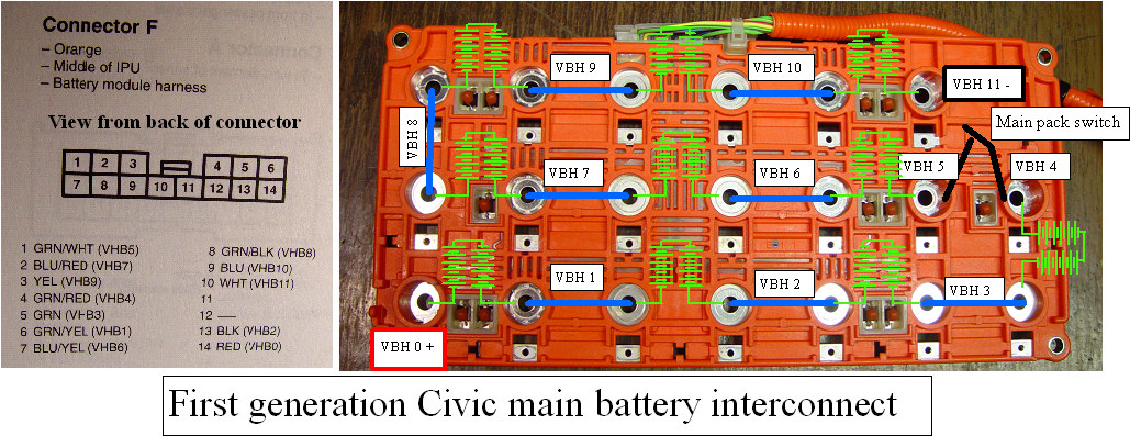
Nice work. You now have a baseline to assess your pack in the future. A simple grid charge to full followed by a 150W discharge to 120V w/150W will tell you if the pack has deteriorated. If there's only minor deterioration, just charge it up and go.
- You would see a voltage peak, but you wouldn't see the -dV. Based on charge times, you likely never got to 100% SoC, but you got close on charge #4 (you need about 30 hours after a deep discharge).
- Did you post these temp data? I didn't see them.
- Voltage drop is proportional to the resistance. Your lowered the resistance, the voltage rose and then began decreasing as capacity was consumed.
- HCH1 connector voltage taps:
Nice work. You now have a baseline to assess your pack in the future. A simple grid charge to full followed by a 150W discharge to 120V w/150W will tell you if the pack has deteriorated. If there's only minor deterioration, just charge it up and go.
#3
04-05-2017, 10:00 AM
Thanks for the HCH1 voltage taps, maybe next time I can do some charts on individual blocks. Thats a lot of work, so we will see when the time comes.
You are right, I was thinking -dV when I said peak. Obviously after seeing how Charge_4 went, I chickened out on the first 3 charges and never even got to the peak.
I am not sure how an extra 6 hours on charge 4 would have made much difference. Can you explain how the extra 6 hours might have helped? I understand balancing the lowest cells by slowly overcharging the full cells, what I don't understand is it was flat for 2 hours already, what is expected from another 6? The temperature increase starting at 18 hours indicates overcharging of at least some of the cells was beginning, so other than some arbitrary time is there some measurable characteristic that implies all cells are fully charged? Not being argumentative, just trying to understand the theory/mechanics behind it. I certainly learned a lot during this process and appreciate the additional discussion and support.
The temps are shown in Charge_2, Charge_3, Charge_4 images. Input is fan side, output is opposite.
#4
04-05-2017, 11:09 PM
You indicated a temperature spike during DIScharge. I don't see it.
Speaking to charge 4, while it looks significant, a 6 deg increase isn't a spike. The chart scale is a little misleading. The significance to the increase is that it was occurring as voltage rate of increase was slowing. This indicates you're getting into the more inefficient charging region (approaching full).
The bottom line is that the ANSI standard for capacity determination involves discharging to 1V/cell at 0.2C and charging at 0.1C for 16 hours. Capacity is then determined by a 0.2C discharge to 1V/cell.
For the 6500mAh rated HCH1 cells, that's 10,400mAh of input. At 350mA, you're even less efficient than you are at 0.1C (650mA), so 10,400 / 350 = 29.7 hours. Due to the increased inefficiency, you're still going to fall short of the charge imparted by 0.1C for 16 hours.
When you get to the high states of charge at low charge current, there is a lot of activity in the 0.00XV range. You actually do get very small -dV, but with 120 cells, you almost never see it. In extremely imbalanced packs, you may. You'll see a peak, a pull back and then another climb. You didn't see that in your case as you didn't do an initial topping charge. The cycling you did likely bottom-balanced the cells and minimized the voltage shenanigans at the top.
With your input temperatures, you're going to see about 85-90 deg when the pack is full.
Regardless, insufficient initial charges aside, you likely did a lot of good for yourself. The improvements in 150W discharges were directly tied to the charge times, so it's hard to say there was any actual improvement, but the final discharge based on only 18.5 hrs of charging puts you at approximately 5250mAh of capacity, which is VERY workable. If balanced, these packs can work well down into the 3000s.
Moving forward you should consider preventative grid charges every 90 days or so with the aforementioned discharge to 120V to compute capacity. If you're over about 4500mAh capacity after a 24 hr grid charge, subsequent cycles are likely unnecessary.
You can drive the fan in the car by powering it with a 10A/12V supply and grounding the PWM line to the negative terminal. This will run the car fan at full blast and make removing the battery unnecessary.
Last edited by S Keith; 04-05-2017 at 11:11 PM.
#5
04-06-2017, 12:03 PM
Now that was exactly the kind of answer I was looking for! Thank you so much for the explanation and the calculations. Makes perfect sense.
The reason you don't see the spike on the discharge is I didn't post the temps for the discharge, and if a 6 degree increase isn't significant on Charge_4, then the 1-2 degree bump I saw is likely very insignificant. I had been paying more attention to the output temp as my thinking was that was the cumulative rise in temperature from all the cells in the middle of the pack that the air was passing over. Maybe that was flawed thinking, but that was my justification why it seemed to be more responsive to the battery state.
With an extra day or two of seat time, there is definitely a significant improvement in assist. It certainly feels like there is extra capacity. For example before this reconditioning accelerating up a hill from a stop at the bottom (minimum of 30 seconds with 1/2+ assist) would pretty much drop a full SoC to roughly 1/3 and require forced charging (i.e. even during light acceleration). Now that same hill will only drop the SoC to roughly 3/4 - 2/3 remaining and still have plenty of reserve for later. Its all subjective, but it really feels so much better.
Do you have any schematic/pics for the connecting the 12V supply for the fan? To be honest I didn't even look at the fan side while I had it open since I knew I was going to be doing it on the bench.
Also, I have seen instructions for bypassing the battery (while in place) so that the DC-DC converter still works within a rpm range. Is there anything out there for doing that if the battery is removed? This HCH1 is my only vehicle so long downtimes are very disruptive.
Thanks again, the feedback has been amazingly helpful!
Last edited by sharrq27; 04-06-2017 at 12:06 PM.
#6
04-06-2017, 07:37 PM
A detectable improvement is expected. Your final discharge had over 5000mAh to 120V, and that should perform very well.
https://cdn.shopify.com/s/files/1/09...47403238190778
Red is (+), black is (-), yellow is tach and blue is PWM. Basically, you short blue to black. The fan is a small leaf blower and require 100W+ when run in this method.
It's possible to remove the pack and spoof the system with only the junction board in an insight, but I don't know if there an analogy for the HCH1.
#7
04-09-2017, 10:08 AM

Is there a reason why, immediately following a discharge to 120V, the car cannot be driven to mostly recharge the pack, and only then finished off with a grid charge the rest of the way? The car can recharge the battery from nada to most of the way charged in a few minutes, whereas my grid charger takes many, many, many hours at 300mA, and the inline 1A fuse in the grid charger harness sets a hard upper limit on how fast any external device could pump charge into the battery.
#8
04-09-2017, 01:22 PM
An HCH1 battery with a resting voltage of 144V or less is completely depleted of any useful energy. My concern is that the 30A demand to fire the ICE up would be pretty hard on the cells.
If you want to speed it up, 2 hours at 300mA will get you close to 10% SoC, then start and charge to full at idle, which is 4-5A. reset 12V and charge 3 times will get you a little above 80% SoC. Then about 5-6 hours on the grid charger should get you pretty close to true 100% SoC.
If you want to speed it up, 2 hours at 300mA will get you close to 10% SoC, then start and charge to full at idle, which is 4-5A. reset 12V and charge 3 times will get you a little above 80% SoC. Then about 5-6 hours on the grid charger should get you pretty close to true 100% SoC.
#9
04-10-2017, 10:37 AM
An HCH1 battery with a resting voltage of 144V or less is completely depleted of any useful energy. My concern is that the 30A demand to fire the ICE up would be pretty hard on the cells.
If you want to speed it up, 2 hours at 300mA will get you close to 10% SoC, then start and charge to full at idle, which is 4-5A. reset 12V and charge 3 times will get you a little above 80% SoC. Then about 5-6 hours on the grid charger should get you pretty close to true 100% SoC.
If you want to speed it up, 2 hours at 300mA will get you close to 10% SoC, then start and charge to full at idle, which is 4-5A. reset 12V and charge 3 times will get you a little above 80% SoC. Then about 5-6 hours on the grid charger should get you pretty close to true 100% SoC.
Please clarify what you mean by "reset to 12V and charge 3 times".
"Reset to 12V" is unambiguous, but what does "charge" in the 2nd part mean? Presumably idle at >3K RPM but to what end point? If it goes to 100% SOC on the meter why repeat the cycle? Also is that
reset charge charge charge
or
reset charge reset charge reset charge
?
Thanks.
Last edited by pasadena_commut; 04-10-2017 at 10:41 AM.
#10
04-10-2017, 10:51 AM
reset
charge at idle until it stops charging
reset
charge at idle until it stops charging
reset
charge at idle until it stops charging
grid charge for 5-6 hours to top it off.
If it will not charge at idle, charge at whatever rpm provides charging. For both Insight and HCH2, the above works with no throttle input. I don't know if the HCH1 will.
The reasons for three resets/charges are:
1) you may not trigger a positive recal with one.
2) even if you trigger a positive recal with one, a 3 minute idle charge at 4-5A is equivalent to about 40 minutes of charging at 300mA - it ensures that as many cells as possible are at or above 80% SoC. I also don't trust the SoC computation based on a single 12V reset. I think it's a little conservative.
charge at idle until it stops charging
reset
charge at idle until it stops charging
reset
charge at idle until it stops charging
grid charge for 5-6 hours to top it off.
If it will not charge at idle, charge at whatever rpm provides charging. For both Insight and HCH2, the above works with no throttle input. I don't know if the HCH1 will.
The reasons for three resets/charges are:
1) you may not trigger a positive recal with one.
2) even if you trigger a positive recal with one, a 3 minute idle charge at 4-5A is equivalent to about 40 minutes of charging at 300mA - it ensures that as many cells as possible are at or above 80% SoC. I also don't trust the SoC computation based on a single 12V reset. I think it's a little conservative.


